BasicStamp and 633

Loki008

New member
Its easy to lose sync with the receive packets, but why should the display ever fail to react correctly to a known good sent packet?
Thats the part that is frustrating me as well. The "Ready to start?" and "Packet Recieved" has worked 100% of the time. the " " "Up" "Down" ect were working but stopped working. It really has my head pounding becasue my gut tells me something is defective the way things have been working, yet my head says there is an interface issue as the display seems to work on the PC with wintest.

cosmic, have you tried this display with a basic stamp, or are you commenting based on testing with the PC?

If i can get confirmation that the code provided works it would really help in my trying to figure out whats wrong.
Looking for additional LCD resources? Check out our LCD blog for the latest developments in LCD technology.
 
cosmic, have you tried this display with a basic stamp, or are you commenting based on testing with the PC?
I am commenting based on using WinTest on a PC.

(rant on) I have no direct experience with the Stamp processors, but my experience with trying to help others use Stamps has been very frustrating. I would not touch one with a ten foot pole. (rant off)

I can only surmise that there is something about the way the Stamp sends the packets that makes them invalid part of the time. CF Tech's idea of using the WinTest packet debugger as a listener is a good one. You could alternate between monitoring the 633 responses, and the Stamp's sendings (by changing which line is connected to the PC port's RxD input).
 

Loki008

New member
Ok, i think i finally cracked this. When i got home i wired the project up again, and did made a tweak to the code, changing the length of the STR to 8 rather than 3, and it appears to be working.

I will have to test the old homework board tomorrow to see if it was an issue with the basic stamp i was working on at work, or more likely there was just a bad wire somewhere. but at this point it appears to be working.

Thanks everyone for their help.

*If anyone else tries to use this code, even with the new board and wiring the packetstring/3 does not work for me. I am finding /8 is working 98% of the time, i do occasionally do get an invalid response, but i think that has to do with the timing of the program and catching a peice of the "button released" packet if i am cycling rapidly between key presses.
 

Loki008

New member
I am commenting based on using WinTest on a PC.

(rant on) I have no direct experience with the Stamp processors, but my experience with trying to help others use Stamps has been very frustrating. I would not touch one with a ten foot pole. (rant off)
The issue i seem to be having is that the basic stamp is limited in its processing in terms of not having hardware interupts and being linear in its design. It cant listen to the serial port for packets while doing other things. I think its a great platform for tinkering with automation and such. Parallax has a higher end chip called the propeller which has 8 cores which would work much better for a device like this, you could dedicate a core to serial communication with the device which i think would eliminate the communication issues we are seeing trying to get this product to work with the basic stamp.

The other thing is that maybe someone at crystalfontz should contact parallax about a custom firmware and some supported code for sale through the parallax store. I really think these would sell well as it is a much more polished LCD / Keypad than what they currently offer, that and since parallax works quite a bit with the local schools in getting the product out there with their Stamps in Class program i can see it being used in those type of projects.
 
USB LCD Displays - Graphic and Character LCDs with a Keypad

CF Tech

Administrator
i do occasionally do get an invalid response, but i think that has to do with the timing of the program and catching a peice of the "button released" packet if i am cycling rapidly between key presses.
Keep in mind that you can use 633_WinTest to shut off release key reporting, then save that as the boot state.
 

Loki008

New member
Ok, i think i finally cracked this. When i got home i wired the project up again, and did made a tweak to the code, changing the length of the STR to 8 rather than 3, and it appears to be working.

I will have to test the old homework board tomorrow to see if it was an issue with the basic stamp i was working on at work, or more likely there was just a bad wire somewhere. but at this point it appears to be working.

Thanks everyone for their help.

*If anyone else tries to use this code, even with the new board and wiring the packetstring/3 does not work for me. I am finding /8 is working 98% of the time, i do occasionally do get an invalid response, but i think that has to do with the timing of the program and catching a peice of the "button released" packet if i am cycling rapidly between key presses.
Ok, i think i am just going to return this display. I just wired it up again and its acting flaky again. Its a pitty, i would love to use this display, but it just will not interface with the basic stamp.

I just cant find any pattern or reason for the behavior.
 

chrisdlove

New member
Parallax BS2P48 & CFAH1602A-YYH-JT 2X16 LCD display Initialization code

Hello,
I am new to the forum and hoping someone can point me to a link where i can find the info i am looking for. I purchased a simple 2X16 LCD display CFAH1602A-YYH-JT. I am using it with a Parallax BS2P-48 micro-controller and wish to wire and write software to write to the display. I am including the simple wiring diagram employed as well as the code that Parallax offered.
I am using this in 4 bit mode, 2 row.

I compared the parallax example code with the Crystal fontz initialization code for 4-bit usage and it is pretty close so something minor must be missing. When i run the code on a wired LCD display, it lights up but does nothing.

PARALLAX INITIALIZATION CODE

' -----[ I/O Definitions ]-------------------------------------------------
LCD_Enable PIN 0

' -----[ Initialization ]--------------------------------------------------
'Turn on LCD, clear screen, turn back light on
PAUSE 1000 ' PAUSE FOR 1 SECOND
LCDCMD LCD_Enable, %00110000 ' Initialize LCD
PAUSE 5 ' PAUSE FOR 0.5 SECOND
LCDCMD LCD_Enable, %00110000 ' Initialize LCD
PAUSE 0 ' PAUSE FOR 0 SECOND
LCDCMD LCD_Enable, %00110000 ' Initialize LCD
PAUSE 0 ' PAUSE FOR 0 SECOND

LCDCMD LCD_Enable, %00100000 ' Set data stream to 4-bit mode
LCDCMD LCD_Enable, %00101000 ' Set LCD to 2 line mode; 5X8 font
LCDCMD LCD_Enable, %00001100 ' Set LCD to no-cursor mode

LCDOUT LCD_Enable, Lcd_Cls, ["W"] ' Write "W" to the LCD display

END

----------------------------------------------------------------------------------

' -----[ Initialization ]--------------------------------------------------
CRYSTAL FONTZ INITIALIZATION CODE

LCDCMD LCD_Enable, %00100000 ' set to 4-bit operation
LCDCMD LCD_Enable, %00100000 ' Set to 4-bit operation and select 1-line display and character font
LCDCMD LCD_Enable, %00001110 ' Turn display on, turn cursor on, no flashing cursor
LCDCMD LCD_Enable, %00000110 ' Increase address by 1, shift cursor to the right after writing to DD RAM/ CG RAM

LCDOUT LCD_Enable, Lcd_Cls, %01010111 ' Write "W" to the LCD display

END
 

Attachments

CF Tech

Administrator
Typically pin 3 (Vo) needs to be at ~1v. Can you check that first?

So, you have tried both the Parallax example and the Crystalfontz example?

Where did the Crystalfontz example come from?
 

chrisdlove

New member
Good day CF Tech,
the Parallax micro-controller takes care of the Enable (E), Read Strobe (RS), and Read/Write (R/W) pins if you use a a preset group of pins, P0-P7, wiring diagram given in one of my attachments. Parallax has a few commands you can utilize then based on this pin grouping: LCDCMD which send 4/8 bit data to configure the display and LCDOUT which send data to the display. Parallax only operates on 4-bit data so it needs to configure the display to operate in this mode since it utilized DB0-DB3 or DB4-DB7 data bus.

To answer your question, I utilized the 4-bit initialization mode and display example shown on the top half of the CrystalFontz CFAH1602A-YYH-JP Revision A Revision 1.0 Decembr 2007 manual Page10, screen shot attached. I followed the command codes given, however substituted the Parallax commends to deliver these codes. I excluded the RS, R/W, and enable bits as these are managed via the commands, LCDCMD and LCDOUT.

I will check the voltage on Vo and reply later today.
 

chrisdlove

New member
Hi CF Tech,
i apologize for the delay as i have been extremely busy and now am leaving on business for a few days. I have rewired the entire circuit including the contrast segment as described in the Crystal Fontz manual and will double check connections and coding and try a few different variations. I will also ensure that the input voltage to Vo is approx. 1V DC. I will try to run all these test this weekend and reply here. Given i can get it working i will post the full circuit and code for other to use.

Thanks for the support :)
Chris.
 

chrisdlove

New member
Parallax BS2P24 - CF LCD display 2X16 - Hello World Init details

Hi CF Tech,
I have completed the adjustment and found Vo to be near +5V. After reducing this to near 1.0V the LCD display worked correctly. As promised, code and pictures are included for others to benefit from.

‘ Reference Auxiliary set of pins using MAINIO Command
LCD_Enable PIN 0 ' P0 -> Pin 5,BS2P40->Pin 10,SX48BD - LCD Enable
PIN1 PIN 1 ' P1 -> Pin 6,BS2P40->Pin 11,SX48BD - Not used
LCD_R_W PIN 2 ' P2 -> Pin 7,BS2P40->Pin 12,SX48BD - LCD Read/Write pin 2
LCD_RD_STROBE PIN 3 ' P3 -> Pin 8,BS2P40->Pin 13,SX48BD - LCD Read Strobe pin 3
LCD_DB4 PIN 4 ' P4 -> Pin 9,BS2P40->Pin 14,SX48BD - LCD Data bus pin 4
LCD_DB5 PIN 5 ' P5 -> Pin 10,BS2P40->Pin 15,SX48BD - LCD Data bus pin 5
LCD_DB6 PIN 6 ' P6 -> Pin 11,BS2P40->Pin 16,SX48BD - LCD Data bus pin 6
LCD_DB7 PIN 7 ' P7 -> Pin 12,BS2P40->Pin 17,SX48BD - LCD Data bus pin 7

' -----[ LCD Constants ]-------------------------------------------------------
Lcd_Init CON $30 ' Initialize LCD
Lcd_CLS CON $01 ' Clear LCD
Lcd_4_Bit CON $20 ' Set data stream to 4-bit mode
Lcd_2_Line CON $28 ' Set LCD to 2 line mode; 5X8 font
Lcd_No_Cursor CON $0C ' Set LCD to no-cursor mode
Lcd_Auto_inc CON $06 ' Set LCD to auto-increment cursor
Lcd_Row1 CON $80 ' Move LCD to Home position (Row 1)
Lcd_Row2 CON $C0 ' Move LCD to Home position (Row 2)

'Turn on LCD, clear screen; turn backlight on
PAUSE 500
LCDCMD LCD_Enable, Lcd_Init
LCDCMD LCD_Enable, Lcd_4_Bit
LCDCMD LCD_Enable, Lcd_2_Line
LCDCMD LCD_Enable, Lcd_No_Cursor
LCDCMD LCD_Enable, Lcd_Auto_inc
LCDOUT LCD_Enable, Lcd_Cls, ["Hello World!"]
LCDOUT LCD_Enable, Lcd_Row2, ["How are you?"]
END


Dear CF Tech,
i wish to create my own custom character. Can you please advise steps do store, access and display this?
Thx,
Chris.
 

Attachments

CF Tech

Administrator
Custom Characters with BASIC Stamp

Chris:

Awesome that you have it going. I'll try my best to help with the custom character bit.

First, you have to set the address to the correct location, then write the 8 bytes. Here is my best guess, but I am not sure about sending the 8 bytes in hex.


Code:
' -----[ LCD Constants ]-------------------------------------------------------
. . . 
Lcd_Cust_0 CON $40 ' CGRAM address for custom character 0
Lcd_Cust_1 CON $48 ' CGRAM address for custom character 1
Lcd_Cust_2 CON $50 ' CGRAM address for custom character 2
Lcd_Cust_3 CON $58 ' CGRAM address for custom character 3
Lcd_Cust_4 CON $60 ' CGRAM address for custom character 4
Lcd_Cust_5 CON $68 ' CGRAM address for custom character 5
Lcd_Cust_6 CON $70 ' CGRAM address for custom character 6
Lcd_Cust_7 CON $78 ' CGRAM address for custom character 7

. . . 

'Set the custom character to make a sideways solid V-like shape
'I am not soure how to send an array of hex bytes, you need to send 8
LCDOUT LCD_Enable, Lcd_Cust_0, [$3F,$1F,$0F,$07,$03,$01,$03,$07]
Oh, I was trying to find out how to initialize an array using hex in basic stamp language and came on this:

http://www.parallax.com/go/PBASICHelp/Content/LanguageTopics/Commands/LCDOUT.htm

Another use for the LCDOUT command is to access and create custom characters. The Hitachi 44780 controller has a built-in character set that is similar to the ASCII character set (at least for the first 128 characters). Most of these characters are stored in ROM and are not changeable, however, the first eight characters (ASCII 0 though 7) are programmable.

Each of the programmable characters is five pixels wide and eight pixels tall. It takes eight bytes to describe each character; one byte per row (the left-most three bits are ignored). For example, the character at ASCII location 0 is defined by the bit patterns stored in bytes 0 through 7 of Character Generator RAM (CGRAM). The character at ASCII location 1 is defined by the bit patterns stored in bytes 8 through 15 of CGRAM, and so on.

To create a custom character, use some graph paper to plot out the bit pattern (on and off pixels) in a 5 x 8 pattern, as shown in below. Then calculate the corresponding binary value of the bit pattern for each of the eight rows of character data.

Character Cell Structure and Data


After the data is calculated for each character (8 byte values per character), use the LCDOUT command with the "Move To CGRAM Address" instruction to insert the data into the character's CGRAM locations. For example, the code below will store the character shown in above into character 0's CGRAM data locations. Then it will place the cursor back on the display (DDRAM) and print the character on the screen.

Code:
  LCDOUT 1, 64+0, [00, 10, 10, 00, 17, 14, 06, 00]
  LCDOUT 1, 128+0, ["Custom Char: ", 0]
The number 64 in the Command argument is the LCD's "Move to CGRAM Address" instruction and the 0 that is added to it is the location of the first row of data for the character 0. The LCDOUT command will write the first OutputData value (00) to this location, the second OutputData value (10) to location 1, etc. If we wanted this custom character to affect character 1, instead of 0, we'd have to adjust value of the "Move To..." command, i.e., 64+8. To affect character 2, we'd use 64+16.

To try the example above, don't forget to execute the LCD initialization code (shown in the LCDCMD description) first and never forget to move the cursor back to the screen (as with the last command, above) when you're done writing the character data to CGRAM.
 

Attachments

chrisdlove

New member
Hi CF Tech,
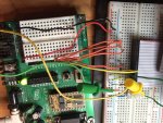
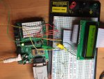
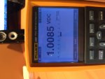
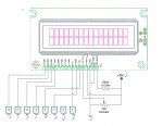
I have now completed loading and displaying the custom characters using the first three positions of the 7 programmable position in CGRAM. Again, sharing the code and pictures for the rest of the CrystalFontz users.No change the to the schematic shared earlier. The LCD initialization must be completed to prepare the LCD display to operate in 4 bit mode. As mentioned by CF tech, the Vo must be near 1.0V DC else contrast is too high and although the display is working it just looks like a super bright screen!

**Note: ignore the "h" showing in picture as i simply was playing with printing character "104" = "h" on screen during one of my tests....

' -----[ LCD Constants ]-------------------------------------------------------
Lcd_Init CON $30 ' Initialize LCD (use PAUSE 5 after)
Lcd_CLS CON $01 ' Clear LCD (use PAUSE 5 after)
Lcd_4_Bit CON $20 ' Set data stream to 4-bit mode
Lcd_2_Line CON $28 ' Set LCD to 2 line mode; 5X8 font
Lcd_No_Cursor CON $0C ' Set LCD to no-curson mode
Lcd_Auto_inc CON $06 ' Set LCD to auto-increment cursor
Lcd_Row1 CON $80 ' Move LCD to DDRAM Home position (Row 1)
Lcd_Row2 CON $C0 ' Move LCD to DDRAM Home position (Row 2)
LcdCC0 CON $40 ' define custom char 0, - wave logo
LcdCC1 CON $48 ' define custom char 1, - up arrow
LcdCC2 CON $50 ' define custom char 2, - down arrow

' Load custom characters in CGRAM (available spots are 0-7)
LCDOUT LCD_Enable, LcdCC0,[$00, $03, $06, $0C, $0C, $0E, $1E, $11] ' Writes Character generation RAM position "0" Wave
LCDOUT LCD_Enable, LcdCC1,[$04, $0E, $15, $04, $04, $04, $04, $04] ' Writes Character generation RAM position "1" UP ARROW
LCDOUT LCD_Enable, LcdCC2,[$04, $04, $04, $04, $04, $15, $0E, $04] ' Writes Character generation RAM position "2" DN ARROW

LCDOUT LCD_Enable, Lcd_Row2, ["Custom chars:", 0, 1, 2] ' Display Wave, up arrow, down arrow custom characters on screen
Pause 5000 ‘ pause 5 seconds to see the characters

‘Scroll 3 waves across Row 1 on LCD
LCDCMD LCD_Enable,Lcd_Cls
FOR counter = 0 TO 15 ' Scroll waves across screen
LCDOUT LCD_Enable, Lcd_Row1+counter,[0,0,0] :pAUSE 165 ' scrolls 3 wave custom chars across
' screen with small pause
LCDCMD LCD_Enable,Lcd_Cls ' clear screen
NEXT
END
 

Attachments

chrisdlove

New member
Hello CF tech,

Adding a follow-on comment:

I've connected the CrystalFontz LCD panel using a straight ribbon cable - about 10" long. One thing i've noticed is that reloading and running the code 10X in a row sometimes cause only LCD Row 1 to be initialized. The top LCD row will become far darker when this happens. The solution to ensure both rows are active is to repeat the command to initialize two rows with a "PAUSE 500" between them. This seems to reliably result in two rows being initialized.

I suppose there is some debouncing going on one of the lines....I've tried longer pauses but the only reliable solution is to repeat the command twice. The other possibility is that there is capacitive charging on the line where the TTL value is in the middle ground. I've seen this happen as well with the Parallax outputs lines. Which root cause is to blame is unclear without an oscilloscope.

Either way, this is a quick fix and sharing so everyone can benefit!

'Turn on LCD, clear screen; turn backlight on
PAUSE 500
LCDCMD LCD_Enable, Lcd_Init
LCDCMD LCD_Enable, Lcd_4_Bit
PAUSE 500
LCDCMD LCD_Enable, Lcd_2_Line
PAUSE 500
LCDCMD LCD_Enable, Lcd_2_Line
PAUSE 500
LCDCMD LCD_Enable, Lcd_No_Cursor
LCDCMD LCD_Enable, Lcd_Auto_inc
LCDOUT LCD_Enable, Lcd_Cls, ["Hello World!"]
LCDOUT LCD_Enable, Lcd_Row2, ["How are you?"]
END


Regards,
Chris.
 

chrisdlove

New member
Parallax BS2P40 to CrystalFontz 2X16

Hello CF Tech,
I've now migrated the breadboard wiring system (shared above) onto a custom PCB board with the same wiring diagram. When i download the Parallax stamp code, it downloads successfully, and i have checked continuity for all 16 pins. The wiring diagram for this portion of the board is shown below.

crystal fontz.jpg

I have checked that the resistance between +5V and the pointer of the variable resistor is very close to 1 K Ohm. The other connections have been checked for continuity and the same code has been migrated and downloaded to the microprocessor. When i power the board, I see a brief flash on the LCD display where it lights up and then goes completely dark (unpowered). This is repeatable. If you happen to have any ideas what may be the reason the LCD display is not working i would appreciate any advice or suggestions. I will continue to troubleshoot and report back anything i find as well.

Thanks kindly,
Chris.
 

CF Tech

Administrator
Typically the pot would be adjusted towards the lower end, not the higher end, as you described. Try slowly sweeping the pot from one end to the other after you have sent the initialization code and some characters.
 

chrisdlove

New member
Hi CF Tech,
I have swept the pot slowly end-to-end and did not see the LCD panel light up as before. I though the resistance between +5V and the sweep pointer had to be 1 kOhm? I believe this is what worked on the prototype board i shared in earlier conversations. I will continue to work on this tomorrow.

thank-you for the suggestion.

Regards,
Chris.
 

CF Tech

Administrator
If one setup works, and the other does not maybe measure and record the voltage of each pin on the old setup, then compare each pin to the new setup.

Also, it is always good to put in test code to toggle each pin individually and make sure that the pin you think it should be changing on the LCD is really the one that is changing.
 

chrisdlove

New member
Good morning CF Tech,
I have made some progress. First, it seems the LCD display i was testing has become damaged. I replaced with a 2nd display and retested on my breadboard setup and confirmed everything works fine. As a second step i have tried setting the pins involved in LCD operation to +5V (without LCD connected) and i am not getting any output (expect +5V). This suggests the CPU is not functioning properly. I will work to resolve this first and report back when i know that is working.

Regards,
Chris.
 
Top