633 crash with a speedy fan

thiam

New member
A fan is connected on the FAN3 connector. The P/N is (if needed) 412J/2H from ebmpapst. This fan can run up to 11000 RPM... quite fast.
I am using WinTest b1.9.
LCD is a 633 (HW:1.5a, FW:k1.9).

In the FAN interface of Wintest, I have :
- RPM unchecked
- PPR 2
- Glitch 1
- Smooth unchecked
- power to 36%
This power gives ~8000 RPM.
After ~1 minute, the LCD seems to reset (backlight off -> on) and the fan goes back to full speed (100% -> ~11000 RPM).

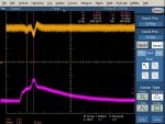
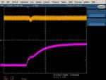
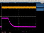
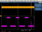
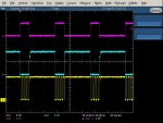
I had a look with a scope on TACK, GND, PWR on FAN3 and they look OK... No bad glitch or strange behaviours.
In the enclosed file, you will see :
1 - TACK
2 - GND
3 - PWM command

Have you seen such a thing ?
Any help would be appreciated.
Thiam
Looking for additional LCD resources? Check out our LCD blog for the latest developments in LCD technology.
 

Attachments

CF Tech

Administrator
That sounds like the reset circuit on the CFA-633 is getting triggered. If the module sees a low voltage, the reset circuit will reset the module.

The return current of the fan can make a drop in the (common) ground conductor of the module, which shows up from the module's point of view as a reduced +5v supply. What current does that fan draw?

Please look at ground and +5v at the pins where they are being supplied to the LCD. Try to see if there is some kind of a transient showing up.

You will want to "float" your scope so the return ground current of the fan is not conducted back through the ground of the scope probe. (If the scope is battery powered, this is easy, if it is line powered, you might need to do the "A-B" thing.)

(Nice scope shot, BTW).
 

thiam

New member
The fan can drive up to 250mA.

You were right, it seems to be a reset of the circuit.
In the enclosed files, you will see that the reset is just after the beginning of the CMOS conduction. There is a glitch on the 5v.

In the shots :
- M1 is 5v-GND (float probes, A-B)
- channel 3 is the PWM output

When it does not crash, you could see that the start of the positive edge causes a small glitch which might be borderline. The negative edge has no impact on the 5v.

-- I will continue with another reply. I do not know how to insert more than 1 file.
 

Attachments

USB LCD Displays - Graphic and Character LCDs with a Keypad

thiam

New member
And now the end (negative edge) of the PWM output.
No impact at all ;-)

Oups... I need to wait 60 secs before another post.........
 

Attachments

thiam

New member
Do you have suggestions to solve this problem ? Add capacitors or something like that ?
Is it relative to the among of current this fan needs or the fact that this is a high speed fan ?

Something weird:
While shutting down my solder iron, I saw BIG glitchs on both PWM output and 5v.
WITHOUT any impact...
I do not understand why the LCD did not reset with such a glitch...
 

Attachments

CF Tech

Administrator
We use an MCP101T-450/TT. It has a finite transient response, so by design it will not reset the processor for very short transients.

You could try adding some capacitance between Ground and +5v at the module.

Also make sure that the return path for the ground currents to the power supply is as short as possible and has as few connections as possible. Preferably find a floppy power lead that comes directly from the power supply right to the CFA-633.

It might be that there is something wrong with the CFA-633. We test them with much mightier fans than those, and the CFA-633 does not reset.
 

thiam

New member
It works with capacitance between gnd and 5v. Good news !

The bad news is that I will need a specific cable to connect the LCD wich will have the capacitor on the floppy connector.

At least, I have a solution.
Thanks you for your help.
 
Top