"TAB" or "COF" style direct solder connector information
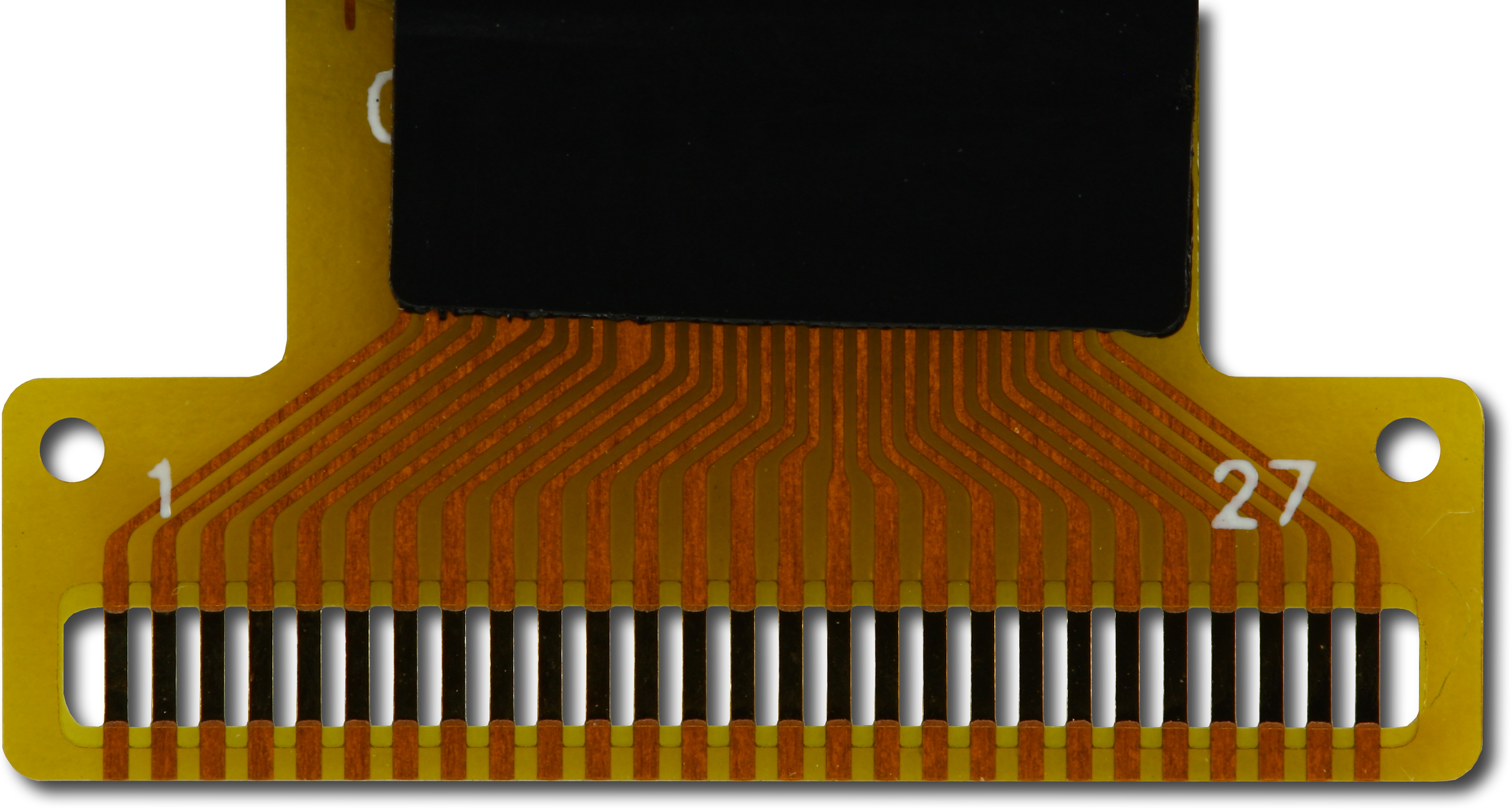
The connector on the CFAL12832C-W-B1 is a "TAB" (tape automated bonding) or "COF" (chip on flex) style flex tail mated with a "COG" (chip on glass) display construction.
This style of connector is designed to be soldered directly to corresponding pads on your PCB by using a hot-bar soldering machine. High volume contract manufacturers will be familiar with this type of construction and its assembly methods.
There are "bondmaster" machines made by APE that are designed for prototype, rework or repair work:
http://ape.com/bondmaster-smd-9000/
We have had good experience with the APE Bondmaster, and their price is very reasonable ($US4K at last check). Here are some other possible solutions:
http://www.fancort.com/Products/Hot-Bar-Soldering-Bonding.aspx
https://www.manncorp.com/hot-bar-soldering/pbs-series/index.php?auto=done
http://www.cherusal.com/tm-111-mkiii/
The process is as follows:
1) the pads on the PCB are tinned
2) the tail is aligned to the PCB using the alignment holes or visually
3) the tail is held in place relative to the PCB with kapton tape
4) the bondmaster head is lowered, applying pressure between the tail and the PCB
5) the bondmaster is "cycled", which means it heats up to the point of melting the solder and then cools down
6) the bondmaster head is raised.
It is possible to hand solder the tail to the PCB. Great care must be taken since the conductors of the tail are completely exposed in the area where they are soldered, as shown in this image:
Kapton tape should immediately be used to secure the tail to the PCB, so the joint cannot flex and break.


