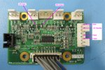
CFA-635 + SCAB - ATX power & reset

Atom2

New member
Hallo Forum,
I have a brand new SCA-635 with keypad & LEDs together with an SCAB-Kit. The problem I am faced with is that I can't turn on the computer with the keypad. The system was bought as a set so all the Jumpers and settings should be o.k. according to the accompanying documentation.

When I provide power to the PSU the LCD screen & the backlight goes on and reads as follows:

Code:
Crystalfontz CFA-635
20x4 + Keypad &
LEDs in 5 1/4" bay
USB V1.6
Also the left uppermost LED is green. I assume that is a good sign - although I would prefer for the screen to be only on when the system is up and running.

The system however does not turn on when I press the green tick button in the middle - it simply stays off. In case I turn on the system by other means I can't power it down by pressing the green tick button for a prolonged time and also can't reset the system by pressing the red cross button.

How would I be able to debug this in order to be able to power up the system.

Any help greatly appreciated.

Many thanks,

Atom2
Looking for additional LCD resources? Check out our LCD blog for the latest developments in LCD technology.
 
USB LCD Displays - Graphic and Character LCDs with a Keypad

CF Support2

Administrator
Did you purchase the module with the WRPWRY14 cable?

This cable provides the standby voltage + ground to the kit, as well as leads for the power and reset pins your system board.

If you did, then we should have contacted you about setting the module up for ATX functionality. If we did not - then my apologies on that.

To ensure the module is configured properly, you'll need to make sure that on the SCAB, JP8 is open and JP8 is closed. For connectivity, you will need a +5v standby to pin 2 of 7 pin header on the SCAB with ground to pin 1. This provides power to the CFA635 so it can pulse the power line. On pin 4 you will connect to the + side of your reset pin pair, and pin 5 will connect to the + side of your power pin pair. The CFA635 in standard configuration for ATX power will pull this line low.

When you have that set up with the module connected to the system, power up your computer. After Windows loads, download and run 635_Wintest:
http://www.crystalfontz.com/software/635WINTEST

Select your module from the ports list. Then Click on the Packet Debugger button.

In part 1, select Command 28
In part 2, type in /240
then click 3: Send packet

In part 1, select Command 4
Clear out any text in Part 2
Then click 3: Send Packet.

To test that the ATX functionality was properly set up and saved, remove the serial connection from the module, but leave the power applied. Press and hold the green check mark (enter). After a short time, the module will display "RESET" and then flash through a power cycle.

That should get you up and running as far as ATX functionality goes.
 

Attachments

Atom2

New member
First of all thanks for your quick reply.

Did you purchase the module with the WRPWRY14 cable?

This cable provides the standby voltage + ground to the kit, as well as leads for the power and reset pins your system board.

If you did, then we should have contacted you about setting the module up for ATX functionality. If we did not - then my apologies on that.

To ensure the module is configured properly, you'll need to make sure that on the SCAB, JP8 is open and JP8 is closed. For connectivity, you will need a +5v standby to pin 2 of 7 pin header on the SCAB with ground to pin 1. This provides power to the CFA635 so it can pulse the power line. On pin 4 you will connect to the + side of your reset pin pair, and pin 5 will connect to the + side of your power pin pair. The CFA635 in standard configuration for ATX power will pull this line low.
I did buy a complete set including the WRPWEY14 cable. But no worries, that was all setup correctly and fine (JP8 open, JP9 closed (NOTE: as per your attached picture; in the text above you say JP8 is open and JP8 is closed) ...

When you have that set up with the module connected to the system, power up your computer. After Windows loads, download and run 635_Wintest:
http://www.crystalfontz.com/software/635WINTEST

Select your module from the ports list. Then Click on the Packet Debugger button.

In part 1, select Command 28
In part 2, type in /240
then click 3: Send packet

In part 1, select Command 4
Clear out any text in Part 2
Then click 3: Send Packet.

To test that the ATX functionality was properly set up and saved, remove the serial connection from the module, but leave the power applied. Press and hold the green check mark (enter). After a short time, the module will display "RESET" and then flash through a power cycle.

That should get you up and running as far as ATX functionality goes.
Thanks for the link, that certainly helped in debugging (though removing the serial connection was not possible as it is a USB version). With the value 240 the LED backlight went off when power is off (good), but the power-on functions still did not work (bad).

After a bit of experimenting, the problem in the end turned out to be that I also had to change the value for POWER_INVERT so the correct value for my system was \248.

I can now use the keypad to turn on the system and also reset behaves as expected. The only mistery still is that the upper-most LED is green when (only) the PSU is connected to line-power but the PC is off. Is this normal and expected behaviour?

Many thanks and best regards,

Atom2
 

CF Support2

Administrator
First of all thanks for your quick reply.
You are most welcome.


After a bit of experimenting, the problem in the end turned out to be that I also had to change the value for POWER_INVERT so the correct value for my system was \248.
The pulse does need to vary from time to time. The "default" is to pull the line low.

I can now use the keypad to turn on the system and also reset behaves as expected. The only mistery still is that the upper-most LED is green when (only) the PSU is connected to line-power but the PC is off. Is this normal and expected behaviour?

Many thanks and best regards,

Atom2
Glad to hear things are up and running for you. The top LED (LED0) being illuminated green is normal operation. It indicates that the standby power is available and the CFA635 is ready to perform it's task.
 
Top