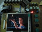
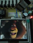
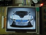
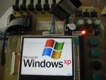
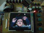
CFAF320240F + ATmega64 = 100% Control :)

maan3k

New member
COLOR QVGA CFAF320240F + ATmega64 = 100% Control :)

COLOR QVGA CFAF320240F + ATmega64 = 100% Control :)
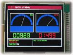
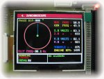
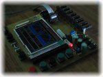
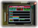
QVGA DEVELOPMENT BOARD WITH CFAF320240FT & ATMEGA64

Here is my latest TFT Development Board with Crystalfonts CFAF320240FT QVGA & ATmega64..

SPECIFICATIONS
********************************
ATMEGA64L-8AI ON-BOARD MAIN PROCESSOR !!!
24 PROGRAMABLE I/O LINES FOR TFT
13 PROGRAMABLE I/O LINES FOR ADDITIONAL ADD-ON MODULE.

8 CHANNELS ANALOGUE SIMULATION
STANDARD ISP HEADER
STANDARD RS232
7 DIGITAL INPUTS (PUSH BUTTONS)
3.3V / 5.0V / 8.0V PROVISION TO ACCOMMODATE WIDE RANGE OF MINI TFTs
24 BIT DETACHABLE DEBUG BOARD FOR INTERFACE VISUALIZATION .
5V DC POWER CONNECTOR FOR LOGIC PROBE
28 PIN RIGHT ANGLE SIL HEADER FOR LCD ON TEST/HACK CAREER BOARD
2 CRYSTALS WITH SELECTOR SWITCH
BUZZER WITH SWITCH ( ENEBLE / DISABLE )

I am designing a Power Control Module for Gensets with Synchronizing & Power Managemant System..

Following are the few options of my proposed module..

MENUES
**********
HOME MENU
ALTERNATOR PARAMETERS
MAINS PARAMETERS
SYCHROSCOPE
DIGITAL INPUTS MONITOR
DIGITAL OUTPUTS MONITOR
ALARM / EVENETS HISTORY
SYSTEM VIEW
COMMUNICATION MONITOR

CONFIGURATIONS MENUS.
*************************
BASIC SETTINGS
COMMUNICATION SETUP
ALTERNATOR PARAMETERS
ALTERNATOR PROTECTIONS
ENGINE PARAMETERS
ENGINE PROTECTIONS
POWER MANAGEMENT PARAMETERS

OTHER PROPOSED FEATURES
************************************
A COMPLETE POWER MANAGEMENT SYSTEM
MULTIPLE GENSET SUPPORT (UPTO 31 GENSETS IN 1 NETWORK)
CAN (CONTROLLER AREA NETWORK ) LINK BETWEEN ALL GENSETS IN 1 NETWORK.
SYSTEM PARAMETERS SHARING ON CAN
PRIORITY SELECTION SYSTEM.
REMOTE DISPLAY MODULES ON RS-485
DIGITAL (CAN) AND ANALOG (L.S LINES) LOAD SHARING OPTIONS FOR THIRD PARTY MODULES. etc ...

Since I have recently got 100% control on this TFT , so I am planning to design more attractive products for power industry..

Since Last 8 Years I am serving the Power Gen Industry and having the worldwide installation experience with world's top power gen brands ,, like W00DWARD , C0MAP etc ..

Visit my site on flickr for more details :):):)

http://www.flickr.com/photos/maan2k

Imran

elect_design_eng@yahoo.com
..
Looking for additional LCD resources? Check out our LCD blog for the latest developments in LCD technology.
 

Attachments

Last edited:

maan3k

New member
COLOR QVGA CFAF320240F + ATmega64 = 100% Control :)

Awesome job. It looks very professional.
thank you ...

Unfortunately ,,, I couldn't found any thread about the color LCDs project on C.F Forums so I initiated ..

I've also done experiments with CFAF176220M and have 100% control :)
I think , I am able to play well with any or all of the C.F TFTs :):):)

Planing to use CFAF320240F in a commercial product !!!

regards

maan
 

ocean

New member
Hi there,

I am working on this display with atmel UC3A0256. 32bit micro.
I have used the demo code to intiatialize the screen and then write the screen fully with blue dots. But the screen remains white.

I have used pwm from the micro to drive the LEDs. I am not sure if my initialization commands are 100% even though I have followed the demo code. I have configured the display with 18bits 8080 mode.

How did you manage to get the display going?
Would you be able to show here your initialization code? are you running in SPI mode or 18bit 8080 mode?

I am thinking I will have my menu pages and buttons saved as .bmp files or some sort of raw files saved in a SD card which I will connect to UC3A0256 via spi. The micro will then read these files and display them (as menu pages) on LCD. Do you think this process would be too slow??
 

maan3k

New member
COLOR QVGA CFAF320240F + ATmega64 = 100% Control :)

Hi there,

I am working on this display with atmel UC3A0256. 32bit micro.
I have used the demo code to intiatialize the screen and then write the screen fully with blue dots. But the screen remains white.

I have used pwm from the micro to drive the LEDs. I am not sure if my initialization commands are 100% even though I have followed the demo code. I have configured the display with 18bits 8080 mode.

How did you manage to get the display going?
Would you be able to show here your initialization code? are you running in SPI mode or 18bit 8080 mode?

I am thinking I will have my menu pages and buttons saved as .bmp files or some sort of raw files saved in a SD card which I will connect to UC3A0256 via spi. The micro will then read these files and display them (as menu pages) on LCD. Do you think this process would be too slow??
Hi Ocean ...

I have used ATmega64 with this display with 16-bit 8080 interface and got success quickly ,,, since I was programming the mini color TFTs of Nokia 6100 (9-bit SPI) & Digital photo keychains (8-bit parallel interface) so I was bit familier with TFTs and quicky adopted this display with 16-bit Parallel interface and about 18-bit interface ,, I am not sure and 've not yet tested ....

I'll shortly post more threads about these displays with SD/MMC interface , which I have successfully tested with this display :) and got 100% results ,,

About your idea of menus & buttons ,,, if you are using really a fast processor as you've mentioned above with 32 bits then whould be fine ,, Since I am using ATmega64 @ 8 MHz so a bitmap of 320x240xrgb from SD card is taking approximate 1.8 seconds to fill the whole display , which looks slower :( :( ,, I'm also not satisfied with SD card reading speed ...

regards

Imran
 

ocean

New member
ah hhm.. ok

i still havnt managed to fix the problem.
so i decided to read in the device code value to see if data communication is realy happening.

ok so i have got 18 pins connected to a crystalfontz lcd screen from atuc3a0256 (atmel 32bit chip).

pins from PB00-PB17 are connected.

I am trying to read PORTB->pvr & DATA_PIN_MASK; so i am reading one of the registers from the LCD (register 0x0000) that has device code in it (device id).

where DATA_PIN_MASK is defined as 0x0003FFFF
and PORTB as &GPIO.port[1];

surprisingly i am getting values offset by 1 to the left?? i have quadruple checked my data bus wirings. i havent missed anything.

why then my values are 1 shifed to the left compared to what i am expecting (the device code to be).
 

ocean

New member
i am getting:
00000000 00000010 01100100 00110010

instead of
00000000 00000000 00011001 00011001 as it says 1919hex in the datasheet.
 
Last edited:

ocean

New member
i just realised something else....if i disconnect the power for the LCD... that is the +ve and gnd supply pins then try to read the 18pins I still get the same:
00000000 00000010 01100100 00110010

does that mean my ssd2119 is not powered on for some reason?? how can this be? i have checked all my wirings.

Does any body have a schematic for the pins i could check against?? This is driving me crazy. spent the whole day today and no progress. :(
 

CF Tech

Administrator
The data lines from the processor can ghost power the LCD controller through the protection diodes, so it is not such a surprise that the data is the same with power on or off.

Sometimes it works good to have a second set of eyes on the circuit. As you show the circuit to them, they may see what the error is, or as you explain it to them, you will see your own trouble.

As far as reading back the right data, but shifted one, see this as a small success, because you are reading the data back at all! Can you stop the read in the middle of the cycle (where the data is supplied to the Atmel by the display), and use a volt meter to see which pins are high and low? Check once right at the display connector, and once at the Atmel pins.

Another good way to check wiring is to have the Atmel write 0x01 then 0x00 repeatedly. Make sure the Do pin on the display is changing (measure at the display connector). Then write 0x02 and 0x00 repeatedly. Check D1. Repeat for all the data and control lines.
 

maan3k

New member
Hi Ocean ..

I'll recommend to use this LCD in 16 bit mode ,, because the provided codes by crystal fontz are for 16 bit interface ,, also have a look on page 78 of SSD2119 ,,, Since you are using 32 bit controller so you need to change little bit in Write_command() & Write_Data() functions ,,,,

Could you post or email me any snap of your driver board of your experiment ???

I've got 100% control on this lcd (pixel by pixel) 65k Color hi hi hi ....
I have also tested the SD card and got the images of 320x240xrgb on this tft ,, but due to the public holiday in my country , I couldn't post them here ,, may be in next week ..

I have tied up CS with GND and RD with VDD , so my interface became more simple ,,

16 + 3 Bits
2 8-Bit Ports & RESET , RS(CD) , WR

And with PS0 .. PS3 , I've used the DIP swich for quick interface configuration ..

Do you have previouse experience of Graphics LCDs ?? STN or TFT ??

The soldering of FPC connector is really a chalange so re-examine it..

Have a look on my page on flickr

www.flickr.com/photos/maan2k

I have also designed one small 24 Bit Debug board (based on 3 x ULN2803 SOIC),, this board is very easy to design ,, have a close look of this board and you can design it very easy ,, this board is very helpful in initial stages of driver development , which provides 24 bit Logic Prob function :) , some times every thing is all right but the controller's configuration is on default manufacturer settings so not responding as required ,, I faced this problem with this board and found the ATmega64 has some default settings which I got to know with the help of this debug board ...

imran
 
Last edited:

maan3k

New member
16-Bit Interface (16+3)

Here is the interface for 16 bit 8080 mode ,, which is tested and 100% guaranted OK ,, see the page 78 of SSD2119 Datasheet.

You can drop one more pin (RESET) if you compromise on software reset or POR ( Power On Reset) .:D:D:D

LCD<--ATmega

CS<--GND
RD<--VDD
RESET<--ANY PORT BIT
CD<--ANY PORT BIT
WR<--ANY PORT BIT

IB0<--GND

IB1<--PORTA.0
IB2<--PORTA.1
IB3<--PORTA.2
IB4<--PORTA.3
IB5<--PORTA.4
IB6<--PORTA.5
IB7<--PORTA.6
IB8<--PORTA.7

IB9<--GND

IB10<--PORTB.0
IB11<--PORTB.1
IB12<--PORTB.2
IB13<--PORTB.3
IB14<--PORTB.4
IB15<--PORTB.5
IB16<--PORTB.6
IB17<--PORTB.7


The above interface is based on 8-Bit MCU , but for 16 or 32 bit MCUs you may use 1 of half port of the controller ...

hope your confusion will be solved and your train will be on RIGHT track ;)


regards

Imran
 

ocean

New member
The data lines from the processor can ghost power the LCD controller through the protection diodes, so it is not such a surprise that the data is the same with power on or off.

Sometimes it works good to have a second set of eyes on the circuit. As you show the circuit to them, they may see what the error is, or as you explain it to them, you will see your own trouble.

As far as reading back the right data, but shifted one, see this as a small success, because you are reading the data back at all! Can you stop the read in the middle of the cycle (where the data is supplied to the Atmel by the display), and use a volt meter to see which pins are high and low? Check once right at the display connector, and once at the Atmel pins.

Another good way to check wiring is to have the Atmel write 0x01 then 0x00 repeatedly. Make sure the Do pin on the display is changing (measure at the display connector). Then write 0x02 and 0x00 repeatedly. Check D1. Repeat for all the data and control lines.
Hi thanks for the reply.
i have used this board from ebay. its excellent. http://cgi.ebay.com/ws/eBayISAPI.dll?ViewItem&item=190328860866&ssPageName=STRK:MEWNX:IT

so thats how I connect the LCD to the board and then run cables to micro.
those protection diodes must be why i am getting those values with or without power. there is nothing wrong with my wiring for the 18pins. I have taken the pins high individually and printed out input values to the pins using hyperterminal and hence my micro is reading the 18pins correctly.

I am getting the feeling the LCD is for some reason not turning on. I will post the schematic now.
 

CF Tech

Administrator
That is a nice looking proto board.

The only thing I have left would be to ask you to send me a list of pins with the voltage you are measuring at each pin. I will ask the engineer to check these.
 

ocean

New member
That is a nice looking proto board.

The only thing I have left would be to ask you to send me a list of pins with the voltage you are measuring at each pin. I will ask the engineer to check these.
its a bit pointless to measure the 18 data pins as they are connected to the micro and micro is in output (low) mode. so all are 0volts.

otherwise:
RD: 3.23v
RESET: 3.23v
CS: 3.23v
RS: 3.23v
RW: 3.23v
PS01 and PS03: connected to +ve
PS00 and PS02: connected to gnd

Vcc to GND reads 3.23v

so i see nothing wrong wiring so far :( unless my display is crooked.
 

CF Support

Administrator
For the sake of argument, can you measure the data lines anyway? I have often thought that my pins were correct, just to check and find that I had some other variable in the way, pulling up on a pin, or that I had inadvertently shared lines with another peripheral that was interfering with my expected behavior for the circuit.
 

maan3k

New member
CFAF320240F + ATmega64 + SD Card = 100% Control :):)

Here we go again......... :):):)
CFAF320240F + ATmega64 + SD Card = 100% Control :)


Since LCD interface is consuming 19 I/Os (16+3) of ATmega64 ,, while I need more bits to interface other peripherals like DS1307 RTC & Serial EEPROMs , CAN Bus , SPI DAC etc ,, so I am designing the new Dev. Board with detachable ATmega Stamp Modules (AT90CAN128 / ATmega1280 / AT32UC3A0256) ,,

hopefully will be ready by next 2 weeks .. :D:D:D

imran
 

Attachments

lohits

New member
CFAF320240F problem setting 255th pixel.

Help me anyone .......:confused:

I am unable to write data on the 255th pixel(horizontal) by passing x and y as horizontal start address ,vertical start address.where x is the horizontal ram address and y is the vertical ram address...... :mad:


Regards

Lohit S
 

25sfk

New member
CFAF320240F 8bit parallel example

Hi all,

I need help with the sample code for your CFAF320204F with 8-bit 8080 parallel interface.
The display is connected to an ATmega644. And the sd card connector is wired as follows:

SD Card Pin 1 --> CS from Mega644
SD Card Pin 2 --> MOSI
SD Card Pin 3 --> GND
SD Card Pin 4 --> +3.3V
SD Card Pin 5 --> CLK
SD Card Pin 6 --> GND
SD Card Pin 7 --> n.c.
SD Card Pin 8 --> n.c
SD Card Pin 9 --> n.c.

The display is working, because I can see the coloured bars on the display (from LCD_test()). But what I'm missing is the picture slide show (some bmp files transfered to sd card) showing on the display.
The pins are defined as follows:

#define MMC_SD_PORT PORTB
#define MMC_SD_CS_PIN 4
#define DDR_INI() DDRB |= _BV(4)|_BV(5)|_BV(7)
#define SPI_CS_Assert() MMC_SD_PORT &= ~_BV(MMC_SD_CS_PIN)
#define SPI_CS_Deassert() MMC_SD_PORT |= _BV(MMC_SD_CS_PIN)

I've done no other changes to the program.
I think the program is hanging in the MMC_SD_Reset() routine.
Is the sd card wiring correct?
Are the pin defines correct?

regards
25sfk
 
Top