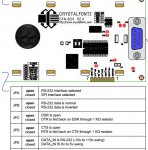
J2 data in format

Miguel

New member
Hi,

I have an CFA634-YFH-KS LCD, hardware 3.3, with RS232 serial interface, and I am connecting it to an embedded system, when I connect the Data In pin of the expansion port J2, it shows nothing the LCD, but when it connects with the serial cable to the cftest if works.

The "DATA IN" pin of the expansion port J2 does not receive serial format rs232 ????

Previously I had a cfa634 version 2.4 and if it worked when I entered data rs232 by the "DATA IN" pin of the expansion port J2.


Best regards
Looking for additional LCD resources? Check out our LCD blog for the latest developments in LCD technology.
 
I will take a stab at helping you, but I don't have this display, and I'm not an expert.

but when it connects with the serial cable to the cftest if works.
I assume this is using the CFtest program on a PC with a standard RS232 serial port. The KS version of the CFA634 has a RS232-to-logic level converter chip on board.

The "DATA IN" pin of the expansion port J2 does not receive serial format rs232 ????
The data sheet (Pg 33) says that the J2 interface is for Logic Level (LL) or LLi (inverted) and the board labels are for the SPI signals.

I believe that the Data In on J2 will not accept a true RS232 signal. When you try to use J2 from your embedded system are you using a true +10/-10 v signal or a logic level signal?

If you are sending J2 a logic level, is it true or inverted? Perhaps the J2 Data In can be used with a logic level signal if you change the "invert" mode using the configuration command \009\004 or \009\005 (see details on Pg 43 of data sheet) while you are using the CFtest app.

Or if that doesn't help, then maybe you need to order the logic level version CFA634-***-KL (or KN).

Crystalfontz doesn't monitor the forum closely, so maybe you should send an email to the support team support@crystalfontz.com or give them a phone call.
https://www.crystalfontz.com/support/
 

Miguel

New member
Hello, thanks for the response Cosmicvoid

Well, I'm using the LCD connected to a PC with a serial to USB converter, and 5v power supply with an external source, it works and you can test the LCD with the Cftest software

My system uses RS232 signals of +10 / -10 v.

It is correct in the data sheet says that the J2 leaves inverted logical signals but I assume that it is for the reference model that is written: "LL - LOGIC LEVEL (CFA634 - *** - KL) AND LLI - LOGIC LEVEL, INVERTED (CFA634 - *** - KN) ".

I assumed that being my model CFA634-YFH-KS, LCD rs232, I should enter this format for that pin, ("DATA IN"), as in the previous LCD model that I have version 2.4.

Regards
 
... My system uses RS232 signals of +10 / -10 v.
You should try sending the +10/-10 signal from your embedded system to the CFA634's DB9 (actually it's a DE9 connector, technically), on Pin 3, and do not try using the J2 header.

I am not sure how the hardware differs between the various CFA634 versions, but if you look at the diagram on Pg 17 of the data sheet, you can see that the LL inputs on J2 don't have the RS232 converter and the +10/-10 v signal could damage the microcontroller input pin.

The older v2.4 data sheet shows a similar block diagram, so I can't understand why the v2.4 display would work with a true RS232 signal on J2.
 

Miguel

New member
Hello,

Apparently I'm going to have to use the DB9 connector on my system.

In the data sheet of version 2.4 refer that there is a jumper (JPE) so that the signal you enter by the "DATA IN" pin of connector J2 is RS232. (pag. 12)

So I assume that version 3.3 no longer brings this jumper that allowed that option.

Regards

Captura.JPG
 
OK, that would explain J2 not working on V3.3. Does your embedded system control the display correctly by using the DB9?
 

Miguel

New member
Yes, it is correct, using the db9 connector the display works, you must also have an external power supply of 5VDC.
 
USB LCD Displays - Graphic and Character LCDs with a Keypad
Yes, but its only necessary if you want the backlight to function. Are you thinking of some alternate way to power the module?
 
Top