The way that LCD displays work is not very closely related to what you are trying to do, so I don't think that will be of much help.
You are just aiming for a muxed array, but I suspect not one that is refreshed at high frequencies, like displays are.
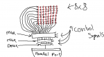
Basically what I am trying to do is have a big grid probably 128x128 to start with, which is made up of motors.
Wow, you want an array of 16384 motors (or "some kind" of electromechanical device)? Do you plan a parallel access, with an 8-bit bus and latches for row and column addressing? Or, perhaps a serial access, where the row & column data are shifted into a long register, and then latched?
Have you given any thought to having 16000 high current drivers? And for inductive loads, you'll need to have clamp diodes across each device to avoid back-emf killing your drivers.
turn on one motor at a time for just a split second, doing so very quickly.
Are you implying that the motors will be PWM controlled? That would complicate your software considerably.
Well, all of this is pretty simple, concept-wise, but the size of the array seems pretty huge for discrete loads (as opposed to something compact like pixels). Perhaps you are making a super-robot.

")
